Subsection 5.2.1 Simple Machine
A simple machine is a device that acts to increase or decrease the amount of output force, \(F_{out}\text{,}\) by the machine compared to the input force, \(F_{in}\) to the machine. Machines can increase the speed of doing work. Machine can transfer energy from one form to another.
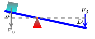
A lever is a simple machine that consists of a beam (or solid rod), a fulcrum (or pivot point), an input force (or effort), and an output force (or load) [Figure 5.2.1]. The beam is placed in such a way that the fulcrum acts as a point of rotation of the beam. The fulcrum remains stationary, while a force is applied somewhere along the length of the beam. The beam then pivots around the fulcrum, exerting the output force on some sort of object that needs to be moved. For example, a crowbar is used to pry up a nail, an effort force is applied to generate an output force, which is what pulls the nail out. Simple machine obeys the principle of conservation of energy, i.e., Input work = output work.
\begin{equation*}
W_{in}=W_{out}
\end{equation*}
\begin{equation*}
\text{or,} \quad F_{in}d_{in}=F_{out}d_{out}
\end{equation*}
\begin{equation}
\text{or,}\quad F_{in}D=F_{out}d \tag{5.2.1}
\end{equation}
where \(D\) is the distance of effort pushed down and \(d\) is distance of load lift up.
There are three basic types of lever.
-
Class 1 Levers: This is a configuration where the fulcrum is in between the input and output forces, such as a seesaw (teeter-totter), catapult, pliers, and scissors [Figure 5.2.2.(a) and Figure 5.2.2.(b)].
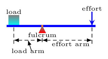
(a) 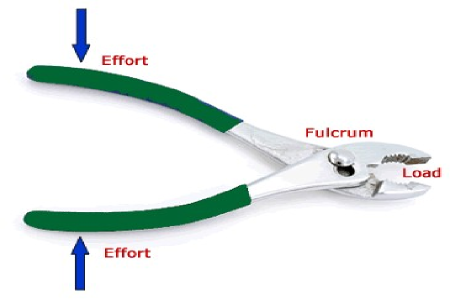
(b) Figure 5.2.2. -
Class 2 Levers: The load comes between the input force and the fulcrum, such as in a bottle opener, crowbar, wheelbarrow, and nut cracker [Figure 5.2.3.(a) and Figure 5.2.3.(b)].
(a) 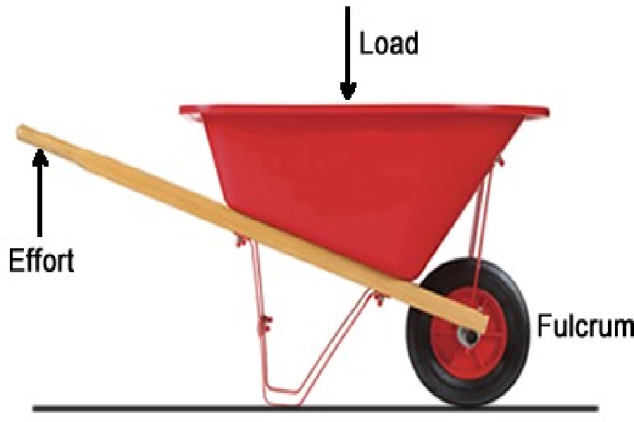
(b) Figure 5.2.3. -
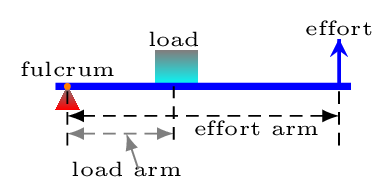
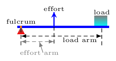
Class 3 levers: The fulcrum is on one end and the load is on the other end, with the effort in between the two, such as with a pair of tweezers, stapler, mousetrap, and broom [Figure 5.2.4.(a) and Figure 5.2.4.(b)].
(a) 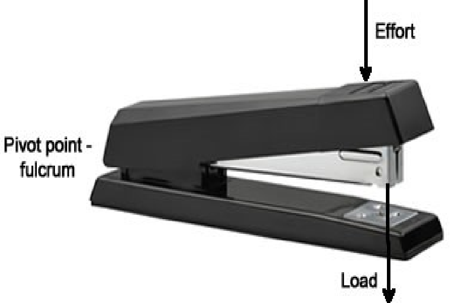
(b) Figure 5.2.4.
Since lever works at rotational equilibrium, the total torque must be zero, i.e.,
\begin{equation*}
\sum\Gamma =0.
\end{equation*}
\begin{equation}
\therefore F_{in}\times e = F_{out}\times l \tag{5.2.2}
\end{equation}
Where \(e\) and \(l\) are lengths of effort arm and load arm, respectively. From eqns. (5.2.1) and (5.2.2), we have -
\begin{equation*}
\frac{F_{out}}{F_{in}} = \frac{d_{in}}{d_{out}} = \frac{e}{l}
\end{equation*}
